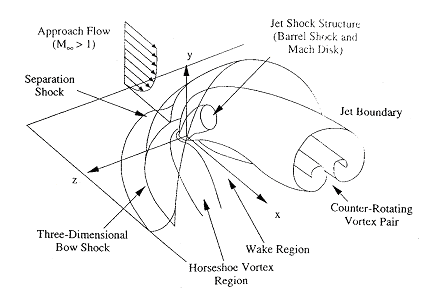
Here we report numerical simulation of transverse fuel injection in the setting of a scramjet engine. We emphasize on the complex flow structure of the transverse injection into a supersonic cross-flow in the vicinity of the injector. We solve the three-dimensional flow equations by using an extended CESE method. The results shown here are based on a mesh of 5.5 millions cells. The simulations were conducted by using a cost-effective Beowulf cluster. The parallel computing is based on the domain decomposition. The numerical results show complex vortex and shock structure. The results compare favorably with the available experimental data in terms of Mach disk location and penetration depth of the fuel jet.

Free stream: air, pressure 41.8 kPa, density
0.86 kg/m3 and Mach number 1.98;
Injectant: air, 476 kPa, density 6.64 kg/m3, Mach number 1.0;
Diameter of the injector nozzle: 2 mm.
CESE method
5.5 million hexahedral meshes
Pressure Contour:
side view: y = 0
end view: x =
2d, x = 4d, x = 6d, x
= 8d
Vorticity Contour:
side view (y-component): y
= 0
end view (x-component): checking plane distribution,
x = 2d, x = 4d, x
= 6d, x = 8d
top view (z-component): z
= 1d, z = 2d, z = 3d
Movie
(6.6 MB GIF format): streamwise contour
(x-component)
Velocity Vector:
side view: y
= 0
end view: x
= 2d, x = 4d, x = 6d,
x = 8d
Concentration Contour:
side view: y = 0
end view: checking plane distribution
and legend, x = 2d, x = 4d, x
= 6d, x = 8d
top view: z
= 1d, z = 2d, z = 3d, z
= 4d
Concentration Profile and Trajectory
กก