![]() Nonlinear stress wave and wavy deformation in impact problems
Nonlinear stress wave and wavy deformation in impact problems
In almost all ultrasound-aided metal processing applications, reduction in the forming forces and/or increases in the formability of the work pieces were reported. For example, in forging, the force was significantly reduced. Early works on aluminum showed that not only the forging force could be reduced to zero, but the barreling could be eliminated. By applying ultrasounds to metal extrusion, the force could be reduced up to 40% and the rate of extrusion would increase up to 300%. In wire drawing and tube-drawing processes, ultrasounds were applied along the wire axis and the drawing forces could be reduced up to 60%. Moreover, the applied ultrasounds improved the surface finish, and the wire production of more complex sections was achieved. In deep drawing, the applied ultrasounds improved the drawing depth up to about 15%. In wall ironing, the ultrasounds increased the maximum area reduction from 63 to 80%.
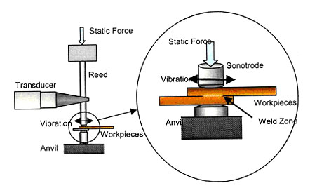
Fig. 1: The ultrasonic welding (USW) process with normal pressure and transverse vibrations.
In the ultrasound welding (USW) process, the ultrasonic vibrations are applied in the direction parallel to the welding interface. Refer to Fig. 1. Because no external heat is added to the specimens and no melting occurs, the USW can be used to weld different metals, e.g., copper to aluminum. The USW has been widely used to bond small-scale nonferrous metals for non-structural uses, e.g., bonding electrical wires, electronic chip packaging, etc. The power input of the conventional USW machines is usually a fraction of 1 kW.
Recent development of high-power ultrasound machines (>10kW) provides a new prospect of the ultrasound aided metal forming/joining processes. For example, a novel USW process [1, 2] is currently under intensive development at Ford Research and Advanced Engineering (RAE). This new USW process, shown by the Ford Motor Company at the International Auto Show 2003 in Detroit, is a promising bonding process for the next-generation automotive body assembly.
1.1 Metal grain and wavy interface in USW
In USW, data consistently showed significant stress reduction up to 80% in almost all processes tested. Microscopic examinations of sectioned and polished specimens showed significant plastic deformation with large-scale roll-ups. The morphology of the plastic deformation resembled those of the Kelvin-Helmholtz instability waves in the presence of shear stresses. Closer examination revealed extensive grain refinement and recrystallization, mixed with clusters of submicron cavities and glassy pores.
Researchers at Ford RAE have shown that aluminum alloy AA6111-T4 sheets could be effectively joined through the process of direct contact between two metallic surfaces under combined static normal pressure and in-plane vibrations in the ultrasound range, with the two metal sheets to be joined ultrasonically oscillated relative to one another in shearing motions. The normal pressures and vibrations are applied to the metal sheets by a sonotrode tip and an anvil. At the end of the process, typical temperatures on the specimen surface are about 80 to 100 oC, which are well below the melting point of aluminum. The temperature increase is mainly due to internal friction.
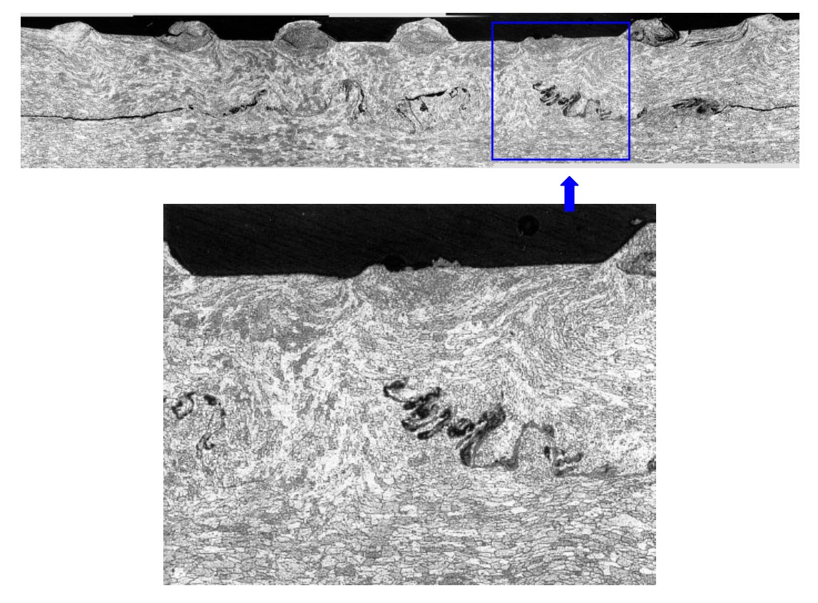
Fig. 2: The nonlinear wave pattern of plastic deformation textures at the contact interface in commercial AA6111-T4 alloys produced by the USW process, from [2].
Microscopic examinations of sectioned and polished specimens showed that significant plastic deformation with large-scale rollups occurred at the interface of the two adjoined aluminum plates. Refer to Fig. 2 for a successfully joined specimen, the interface was made visible by using a marker. The morphology of the plastic deformation resembled those of the Kelvin-Helmholtz instability waves, a continuum mechanics phenomenon in the presence of shear stresses. The corrugated interface provided additional surface for adhesion. The rollup structure allowed the solid aluminums from two metal sheets to be fingered into each other and to form a zipper-like lockup bond.
Further examinations of the "vortex zones" revealed extensive grain rotation and recrystalization with grain sizes much smaller than that of the untreated specimens. In certain regions, the treated metal showed glassy features similar to that of amorphous metals. The recrystalized grains and the glassy spots were mixed with clusters of submicron cavities and pores. There was no evidence of any material melting such as dendrite formation in conventional welding. The observed massive plastic flow and the changes of crystalline structures are not unique to the USW. Similar phenomena (with less intensity if the power input of ultrasound machines is less) occurred in all abovementioned ultrasound-aided metal forming/joining processes. It has been clear that the applied ultrasounds are responsible for the transitory plastic flow and crystalline refinement in these industrial processes.
Fig. 3: The Acousto-Plastic Effect (APE) discovered by Blaha and Langenecker (1955).
Blaha and Langenecker (1955) conducted a compression test on zinc crystals. They applied compression and superimposed with 800kHz vibration on specimen, and observed the 40%reduction in the yield stress. Superimposed with ultrasonic vibrations, metal specimens under compression or tensile loading experience remarkable transitory softening, which sometimes has been referred to as the Blaha effect or the Acousto-Plastic Effect (APE).
Fig. 4: The Acousto-Plastic Effect (APE) reported by Kirchner et al.[3]
Figure 4 shows a typical APE test by Kirchner et al. [3]. The tested specimen was an hourglass-shaped aluminum alloy 6061. A double resonator subjected the specimen to a cyclic loading of 20 kHz. The background loading is a quasi-static compression, increasing at a strain rate of 1x10⁻⁴ sec-1. As shown in Fig. 4, when the vibratory loading was turned on at Point B, the measured mean stress dropped to a lower value at Point C. After cessation of vibrations at Point D, the response of the metal returned back to Point E on the original static stress-strain curve. At Point F, the ultrasonic vibrations were applied again and the measure mean stress dropped to Point G, and so forth.
APE also exists in the process of USW.
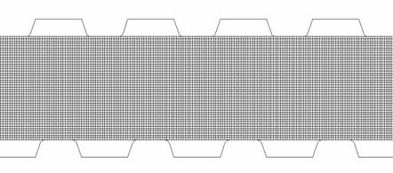
(a) Initial aluminum plates mesh and tips
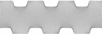
(b) Deformation of aluminum plates
(c) Detailed deformation around one tooth
(d) Normal pressure under compression
Fig. 5: FEM simulating tip penetration in USW
As shown in Fig. 5, the pressure predicted by using ABAQUS and the material properties library is more than 150 MPa, which is much higher than the value measured in experiment -- 60 MPa. The material experiences transitory softening --APE, which cannot be modeled by ABAQUS.
Heretofore, only very limited non-application research works on the APE can be found in the literature [3-10], among which theoretical works aiming to explain the APE [8-10] have been even fewer. All were based on the stress superposition principle in one spatial dimension. The normal stress was decomposed into the background static loading and the superimposed vibrations. Conventional elastic and plastic formulations were employed to model the background loading. The superimposed stress and strain by ultrasounds are modeled by an Arrhenius-type finite-rate formulation for the plastic strain rate [7-10]. The amplitudes of the superimposed stresses and the resultant strain rate depended on the internal friction assessed by empirical models. The approach was based on modifying the static loading by accounting for the averaged effect of the imposed ultrasonic vibrations through empirical relations. In other words, one simply modified the static stress-strain relations by adding the net effect of the superimposed ultrasonic vibrations. The models [7, 10] did not attempt to track the ultrasound waves in the specimens. No analyses exist for examining multi-dimensional problems where nonlinear waves could travel in many directions with respect to the background loading.
1.3 Nonlinear stress wave and wavy interface by numerical model and CESE method
The current research activities address the APE and wavy interface beyond phenomenological descriptions in the previous works. Theoretical and numerical model are employed to clarify the unusual metal deformation characteristics induced by ultrasonic vibrations. A comprehensive continuum mechanics model is developed for macroscopic description of nonlinear stress waves. The approach aims to directly address the dynamic nature of the processes rather than treating the transitory metal softening effect by developing a special constitutive relation to relate the apparent "static stress" to the strain. The space-time Conservation Element and Solution Element (CESE) method, a novel numerical framework for nonlinear hyperbolic systems, will be employed to solve the continuum mechanics equations for the stress waves.
Numerical Results:
Snapshots of the Evolving Interface:
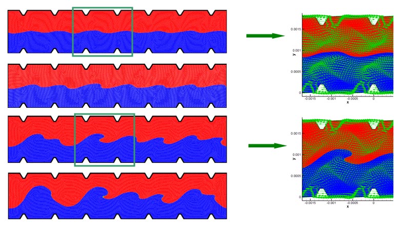
Movie: The Evolving Interface & Zoom In
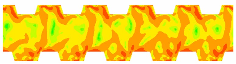
Snapshot of evolving pressure:
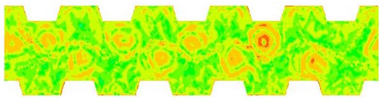
Snapshot of evolving density:
2. Nonlinear stress wave and wavy deformation in impact problems
2.1 1D Impact problem with two components of same material
Fig. 5: Initial condition setting of the one-dimensional impact problem
As shown in Fig. 5, the copper bulk moves from left to right at a specific speed and hits a stationary copper bulk. Owing to metal impact, elastic-plastic stress waves occur in the metal. Initial conditions are as follows:
|
for x <= 0 |
for x > 0 |
| u = 40 m/s | u = 0 |
| p = 0 | p = 0 |
| S11 = 0 | S11 = 0 |
where u is velocity, S11 is the deviatoric stress. The material parameters include the shear modulus
µ = 45 GPa, Young's modulus E
= 122 GPa, and the yield stress ![]() y
= 90 MPa.
y
= 90 MPa.
Numerical Results:
The elastic-plastic pressure waves and density waves.
Solid lines with delta symbols represent the numerical solutions of complete governing equations, solid lines represent the exact values calculated by Udaykumar [11], and solid lines with square symbols are for solutions of simplified model.
Movie: Elastic-plastic stress waves
2.2 1D Impact of three components
Material: Mid-Ocean Ridge Basalt (MORB) liquid ( 0 < x < 0.6) ), and Molybdenum ( 0.6 < x < 1) ).
Initial conditions:
|
for x <= 0.4 |
for 0.4 < x <= 0.6 |
for x > 0.6 |
| u = 543 m/s | u = 0 | u = 0 |
| p = 30 GPa | p = 0 | p = 0 |
Numerical Results:
Density:
Pressure:
Velocity:
Top | Research
| Home
2.3 2D Impact problem with two components
Materials: MORB and Molybdenum.
Initial conditions:
MORB is at rest;
Molybdenum is at rest for x>=0.4;
Shock with Mach 1.163 for x < 0.4
Numerical Results:
Density (y = 0.4, t = 50µs):
Pressure (y = 0.4, t = 50 µs):
Density (y = 0.4, t = 100 µs):
Pressure (y = 0.4, t = 100 µs):
Movie:
Pressure contour
Velocity vector
Domain change
Density contour
2.4 2D Impact problem with three components
Materials: Copper, Aluminum and Water.
Initial Conditions:
Copper and water are at rest;
Aluminum is moving leftward with a speed of 1500 m/s.
Movie:
Density contour
Pressure contour
Al domain change
Copper domain change
1. R. Jahn, L. Reatherford and D. Wilkosz, "Microstructural Evolution at the Contact Interface of Automotive Aluminum Alloys subject to Oscillatory Linear Relative Motion", Presentation at the TMS 2002 Fall Conference, Columbus, OH., (September, 2002).
2. S.-T. J. Yu and R. Jahn, "Plastic Instability Of Wake Morphology In Solid Commercial Aluminum Alloys", Presentation at the TMS 2002 Fall Conference, Columbus, OH., (September, 2002).
3. H. O. K. Kirchner, W. K. Kromp, F. B. Prinz and P. Trimmel, "Plastic Deformation under Simultaneous Cyclic and Unidirectional Loading at Low and Ultrasonic Frequencies" Materials Science and Engineering 68, 197-206 (1984).
4. G. S. Baker and S. H. Carpenter, "Dislocation mobility and motion under combined stresses" Journal of Applied Physics 38, 1586-1591 (1967).
5. T. Endo, K. Suzuki and M. Ishikawa, "Effects of superimposed ultrasonic oscillatory stress on the deformation of Fe and Fe-3%Si alloy" Transactions of the Japan institute of metals 20, 706-712 (1979).
6. T. Ohgaku and N. Takeuchi, "The Blaha effect of alkali halide crystals" Physica Status Solidi. A 102, 293-299 (1987).
7. A. V. Kozlov and S. I. Seliyser, "Peculiarities in the plastic deformaition of crystals subjected to the acoustoplastic effect" Materials Science and Engineering. A 102, 143-149 (1988).
8. A. V. Kozlov and S. I. Selitser, "Kinetics of the acoustoplastic effect" Materials Science and Engineering. A 131, 17-25 (1991).
9. M. Tanibayashi, "A theory of the blaha effect" Physica Status Solidi. A 128, 83-94 (1991).
10. G. A. Malygin, "Acoustoplastic effect and the stress superimposition mechanism" Physics of the Solid State 42, 72-78 (2000).
11. L. B. Tran and H. S. Udaykumar, "A particle-level set-based sharp interface Cartesian grid method for impact, penetration, and void collapse" Journal of Computational Physics 193, 469-510 (2004).
Last Update: 5/9/2006